

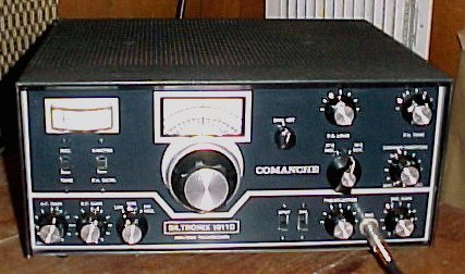
This nice looking Siltronix 1011C tranceiver shown above was the major work horse of many a 10 Meter Radio Amateur and serious CB DX Operator. It features two HF band switch positions from the factory. The 27MHz CB band range in (receive only mode) the lower frequency range position and the lower "Phone" portion of the 28MHz, Ten Meter Ham Band for the high range switch position. The C&D Model output final was supplied with the GE 8950, a new generation "TV type sweep tube" actually designed for Linear RF Operation. Swan 350 owners would often convert their 6HF5 final tube rigs over to the 8950 (required two tubes) for an increased output. I know the mod worked well because I did it on one of my last Stock Swan 350 Amateur Tranceivers.
Compared to the earlier rigs, the 1011C and 1011D pictures clearly show the removal of the left side front CAL-REC-Tune/CW function rotary switch. The rotary function was replaced by a two-position spring loaded REC-TUNE push slider type switch. The new receiver AM SPOT switch now appears next to the ANL switch position. The revised band-switch shows the removal of the top portions of the Ten Meter Amateur Band. We then see the later two-band range selection appear. The internal crystal calibrator and the related rotary function switch also goes away.
Many of the 1011C version rigs were built. You can see them with the early 23 channel CB Band Plan printed on the VFO indicator dial. The 10 Meter Band was often moved down by HF CB Operators to the top half of the "Free Band" CB range. The two band positions combined would cover about 26.925 to 28.025 when properly ranged. The modification of any vfo is not as easily done as many thought. Many hacks would ruin the 1011 VFO stability by experiments with stretching and squeezing the L-C circuits inside the vfo assembly. I have rebuilt many Swan and Siltronix rigs after the typical "golden screw driver" hit. The VFO Stability is always the first to suffer damage after a range-mod attack. Unless your really good ranging VFO L-C Tank Circuits... try to leave the VFO coils/caps alone!
No, the 1011C nor any other model which received the CB band, transmit without an internal modification. It was a simple straight forward mod, often provided by the Radio shop which sold the unit. Alignment was also required for rf stages when moving the top 10 meter vfo range down or the coverse.
The 1011D Siltronix brought updates and the last produced version to the consumer market. Somewhere in the late 70's, the nutty CB boom was crashing down to a dull roar, caused by the Sun Spot Cycle wreaking havoc on the HF CB bands 24 hours a day and the fact that many didn't like what they heard on the radio when they actually got on it. (my how little things have changed...) We've gone through a Sunspot Cycle or two since the late 70's and lost many a Radio Company along the way. Don't forget that Yaesu, Icom and Kenwood/Trio started flooding the Market with new "high feature" radios. Lot's of bells and whistles for arm chair operators to play with. The end of the classic point-to-point built radios era was quickly drawing near.
The 1011D is pretty much the same 1011C radio with some well received updates. There were also at least two different versions of the D model made. The 1011D model updates were the addition of rear panel option jacks, two for external AC devices (like the external counter and/or a boxer fan over the output tube), one 1/8 phone jack for the optional Frequency Counter (FC-1) and a jack to use a pair of internal T/R relay contacts. Some very late D versions started showing up with a retrofit balanced modulator board in place of the previous tube version. Both modulator circuits worked well for me, rarely ever having to re-align the tube version (unless a golden screw driver hack type got there first).
The 1011D VFO dial was redone after a time to show the expanded 23 to 40 channel CB Band while the dual band range switch was left intact. Although the cosmetics were slightly changed, the rig remained pretty much the same circuit layout between the C and D models with small exceptions and the addition of the solid state balanced modulator. I should mention that I've never seen a Siltronix circuit diagram which included the solid state BM circuit, but it appears to be a very common 1496 chip which is a fairly straight forward circuit to use. The chip BM circuit might also have been a product of the Albatross Process mentioned later.
The external Frequency Counter jack can be installed on a 1011C by "a good technician." Some quality coaxial cable (RG-174u), an 1/8 chassis mounted phone jack and a silver mica cap are required.


Last Update: 04/28/04