
Swan - Siltronix history wise, it doesn't get much better than this! Below are some very special pictures of the original Prototype transceiver which I'm told was "never cased". Looks a lot like a half breed Swan 250 and the Siltronix 1011 with a bit of the 350 rig included. I was able to buy the prototype and preserve this special part of radio history at my home. Enjoy and I'll try to comment where possible. Feel free to chime in via Email if you can add to this resource.
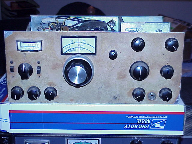
Above is a great picture of the front of the original prototype tranceiver. The band selector is a large knob early five position switch which lived on the Swan 1011 and first Siltronix 1011B. Notice the CAL-REC-Tune/CW multi-function rotary switch between the two vertical slide switches on the center left side. By this time the prototype was built the final front panel layout was pretty much fixed for good. Throughout the model revisions, many of the control postions remained at the same locations.
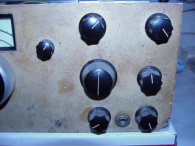
Above you can see a close in of transmitter controls. The carrier balance, bandswitch and driver labels were "updated" (changed) in later versions. The "car bal" label and actual adjustment went underneath the chassis, the location then became the AM mode Carrier Insertion fuction. Band switch selection was 5 positions and the driver label was later changed to Preselector. If you've operated the 1011C and 1010D models, you know the Preselector also tuned the receiver front end. 1011C & 1011D receive was probably similar in operation to the prototype. AM mode zero beat "SPOT" and noise elimintor slide switch "ANL" functions were not on the original rig in the C&D locations. The function of the left side vertical slide switches are unknown but probably the equivalent S-Meter/Cathode metering for at least one.
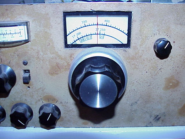
You gotta' love that beautiful vfo dial. Notice the original 23 channel CB band plan indicator squares below their repective actual frequencies. A bit of trivia... notice the "hole frequencies" between channel 22 and 23. These slots later became channel 24 and 25 in the expanded (current) 40 channel cb band plan. The 10KHz hole slots below channel 20, every 4th channel remain "open" for their original radio control (like early rc model airplane) operation. Also note the AM position writen in pencil on the mode switch.
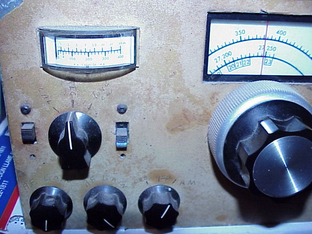
Above is the left hand side of the front panel, Receiver and Metering Controls. The calibrator was deleted from the C & D versions, but the external frequency counter option later appeared on the scene. You can barely see the triangle "delta" symbol in the meter near the 40mA current indication. The Delta was the zero signal final tube idle/resting current position as described by the manual for best linearity. The VFO knob drive was a real sweet geared reduction unit. The meter is a horizontal display movement, not previously seen in other cousin Swan rigs..
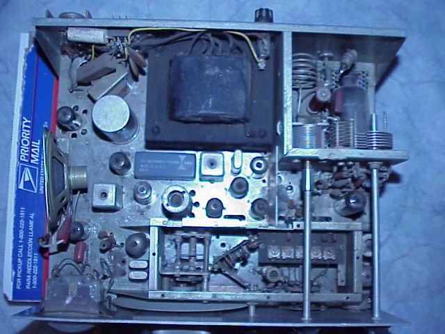
This top inside view shows a direct heritage to the regular Swan Tranceivers and the early circuit layouts tried and tested. Compare this picture to the internal view of the 1011C shown above and you'll see how things changed. Not a tremendous amount. The CF Networks Division crystal filter is an early type. A classic Swan crytal calibrator layout is shown nearby to the right. The cover off internal VFO box view allows us to see how little things changed through to the later models.
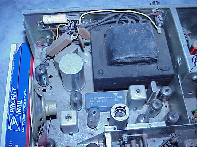
A more detailed look at the top internals near the cinch jones type power plug and the power transformer. You might notice the two odd size power transistors, lead legs poking through the chassis from the rear forward (next the power connector). It appears to be the intention to add the internal dc power inverter for mobile operation. The inverter was deleted at least before the B version made the production line and was probably not on the firs Swan 1011 model shown way above. DC mobile operation was posssible using the regular DC Swan mobile supply. The early audio output tube (top left of the picture) is the interesting choice of a 6GK6. Later the audio tube changed over to a 6GW8 which is a multi-fuction type. This was probably done to include the later added ANL (noise limiter).
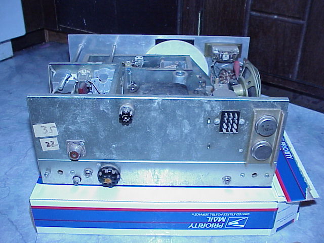
We get a look at the rear panel with the previously mentioned inverter transistors on the right. The 1/4 inch phone jack might have been for an intended CW (code) key never seen on the later 1011C&D versions. I can guess the lower holes on each side are for the S-Meter and Bias set pots. The RCA jack might be for the external VFO input or the 1011D external relay contacts. A smart first guess would be the VFO because of the Octal tube base type plug/jack right next to it. One can't be sure without a closer look in person. The generational 1011 radio versions rear panel layout stayed close to the prototype with minor changes.
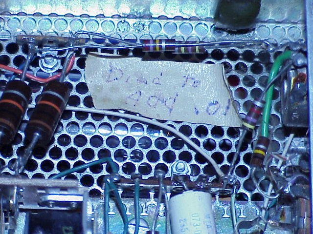
Someone at the factory to add a cap to one part of the circuit under the PA box. All hand wired rigs which required much physical labor to produce. Wonder what their factory quality controls were like...? If you look at the lower right side of the picture, you can see the 1/4 phone jack tip contact. The rear panel RCA jack should also be visible somewhere down there if it was hooked up. Kind of a bad place to park external jacks because that high gain AB1 final circuit is just through the holes on the other side of that screen.
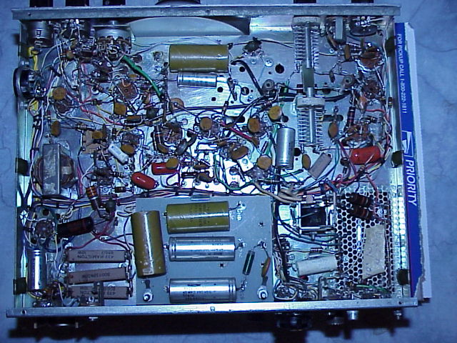
Bottom chassis view of what the untrained eye might call a rats nest. To a typical ham operator of the 60's, this was high tech stuff... very "cutting edge." Actually, these radios are pretty straight forward in layout. Swan and Siltronix Owners Manuals were very well done, and they included details and the circuit diagram. Many people "cut their teeth", electronics wise with a Swan - Siltronix on the bench. Easy to use, easy to find parts for and fix it yourself with the most basic electronics test equipment.


Last Update: 04/28/04